Course: Introduction to Autodesk Fusion 360
🎯 Objective:
Become familiar with Autodesk Fusion 360 as a platform and learn how to create a 3D model.
🔍 What is Autodesk Fusion 360?
Autodesk Fusion 360 is an all-in-one, cloud-based 3D modeling platform that combines:
- CAD (Computer-Aided Design)
- CAM (Computer-Aided Manufacturing)
- CAE (Computer-Aided Engineering)
It is widely used in mechanical design, product design, and rapid prototyping.
🧩 Installation and System Requirements
- Download from: https://www.autodesk.com/products/fusion-360
- Educational licenses are free for students and educators: Link
- Minimum requirements:
- Windows 10/11 or macOS
- 4+ GB RAM (8+ GB recommended)
- Graphics card with DirectX 11 support
- Internet connection (for cloud sync)
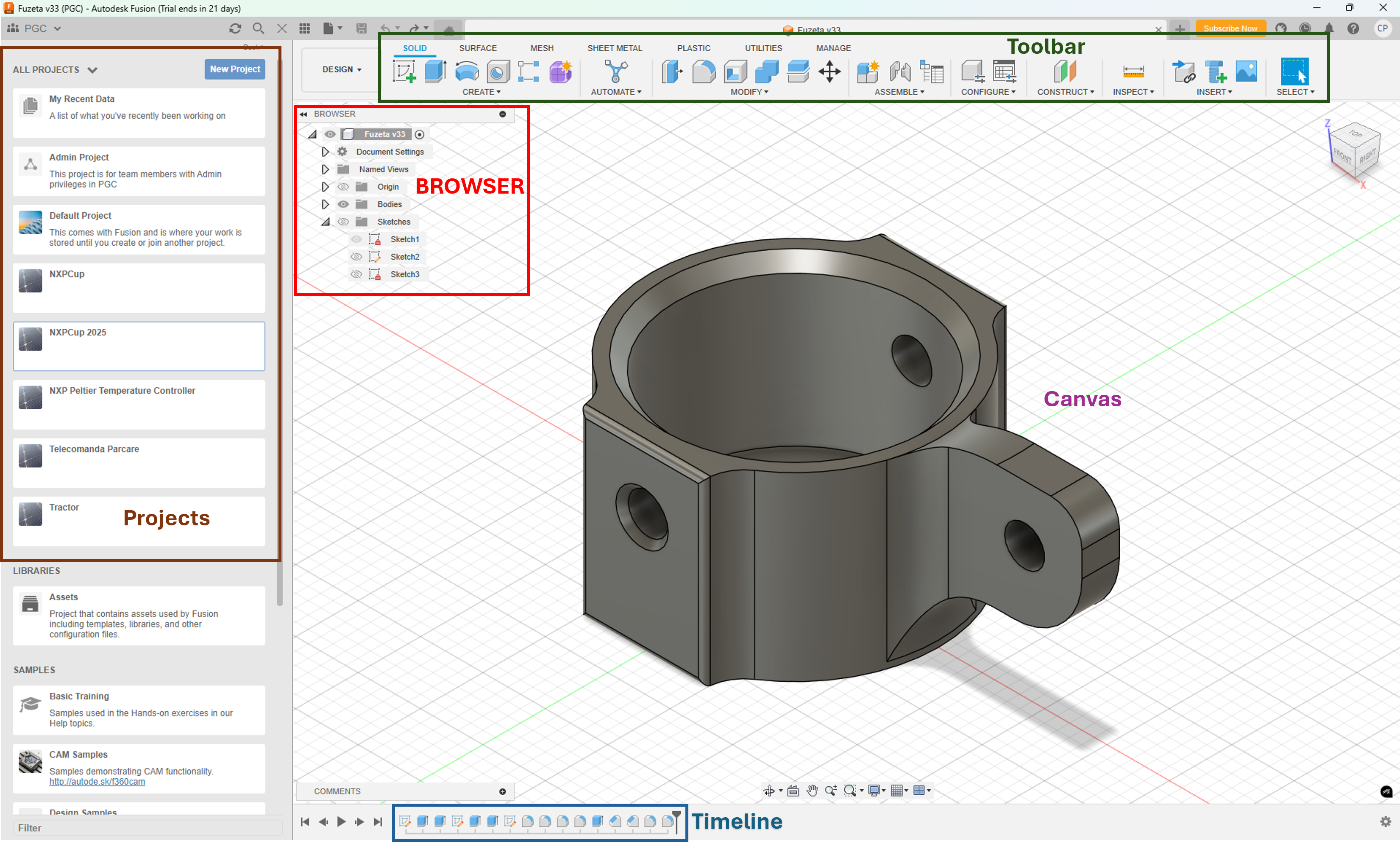
🖥️ Interface Overview
When you open Fusion 360, you’ll see:
- Toolbar: Contains modeling tools depending on the workspace.
- Browser: A tree view of your components and features.
- Canvas: The main modeling window.
- Timeline: History of all modeling operations.
- Projects: Project management panel.
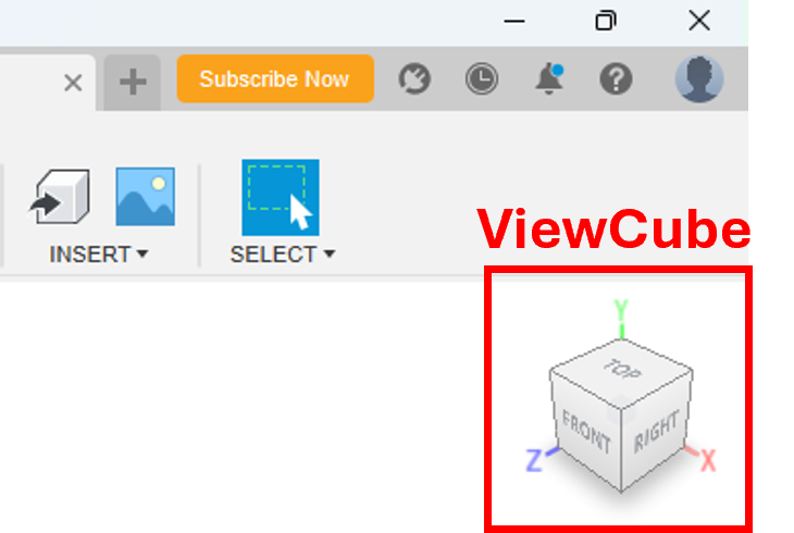
🧭 3D Navigation Basics
You can navigate the 3D space using:
- Orbit: Rotate the view – Hold Shift + Middle Mouse Button
- Pan: Move the view – Hold Middle Mouse Button
- Zoom: Scroll the mouse wheel
Also, use the ViewCube in the top-right corner to switch views.
✏️ Creating a 3D Logo for Your Team in Fusion 360
🧱 Main Steps
- Sketching: The starting point for most 3D modeling tasks. Create a 2D profile on a plane.
- Extruding: Turn the 2D sketch into a 3D solid by pulling it in a specific direction.
🔹 Step 1: Create a New Design File
- Open Fusion 360.
- Go to File > New Design or press
Ctrl + N. - Save the file (
Ctrl + S) with a meaningful name likeSketch_Extrude_Example.
🔹 Step 2: Create the Logo Body
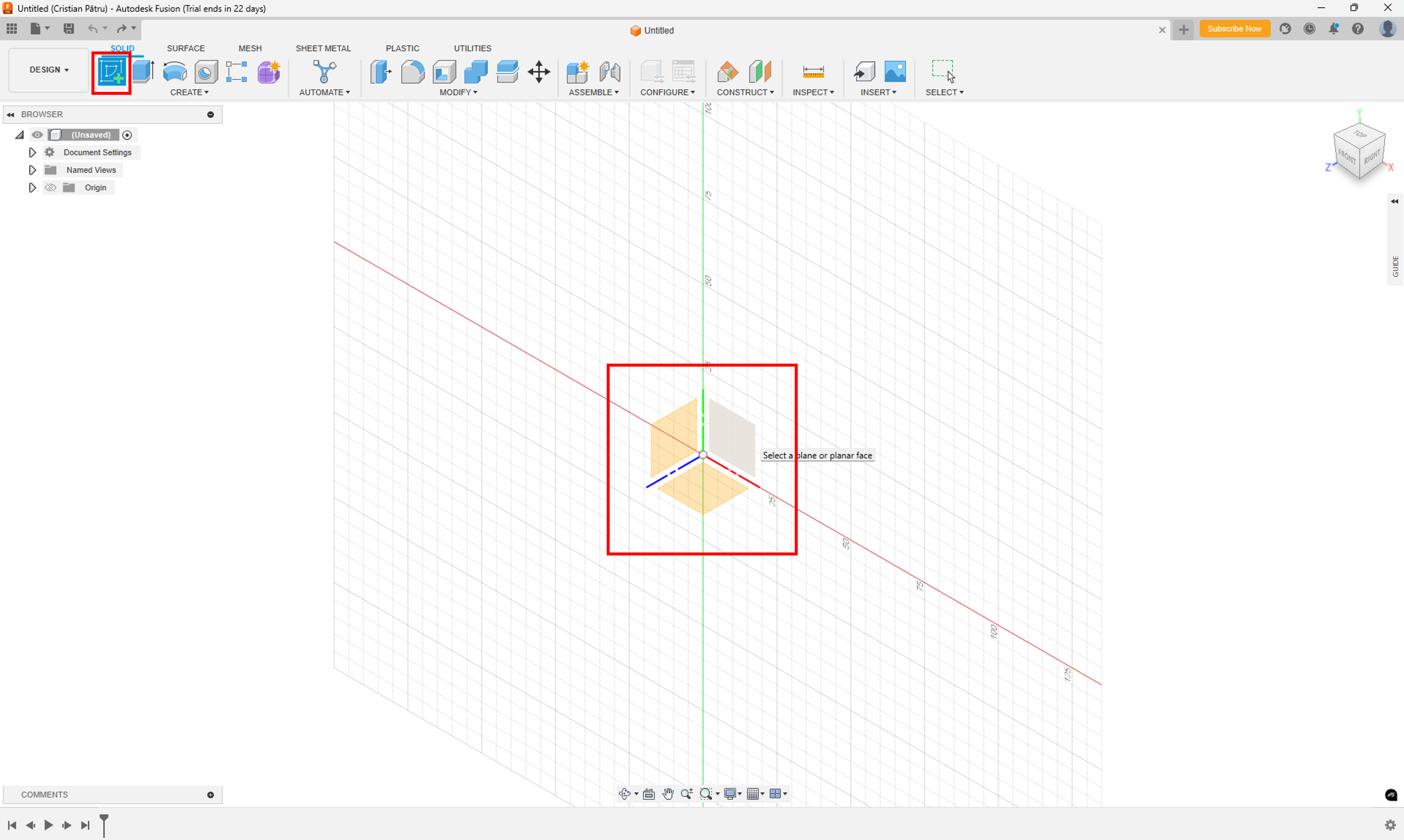
1. Create a New Sketch
- Click on the “Create Sketch” button in the toolbar.
- Select a plane to draw on:
- XY (top view)
- XZ (front view)
- YZ (side view)
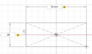
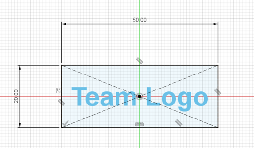
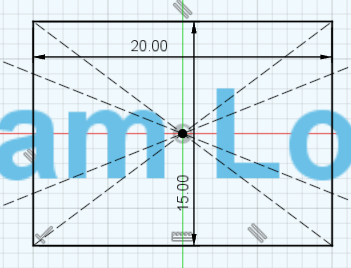
2. Drawing the Base Shape (Rectangle)
Use the sketch tools from the Sketch menu to create the base shape:
- From the Sketch menu, select the Rectangle tool.

- Choose the Center Rectangle option.
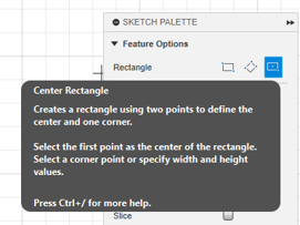
- Draw a rectangle with dimensions 50 x 20 mm.
3. Adding the Logo Text
- Select the Text tool from the Create menu.
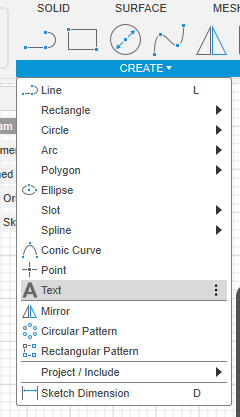
- Type the desired text and choose your preferred font and style.
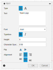
- Position the text inside the rectangle.
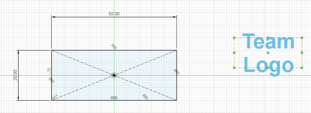
4. Centering and Applying Constraints
To keep the logo in place even if the rectangle is resized:
- Use the Constraints tool to center the logo inside the rectangle.
- Apply corner constraints to align the logo with the rectangle.

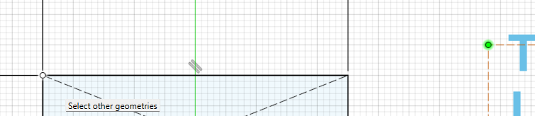
- Final constrained sketch result:
5. Exit Sketch Mode
Once the sketch is complete, exit sketch mode by clicking Finish Sketch.

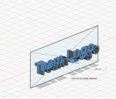
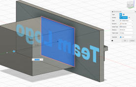
6. Extrude the Text
- Select the Extrude tool from the Create menu.

- Select the text to extrude.
7. Extrude the Base (Rectangle)
- Extrude the rectangle to create a 3D plate for the text.
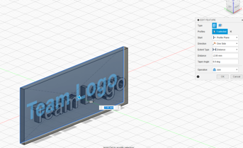
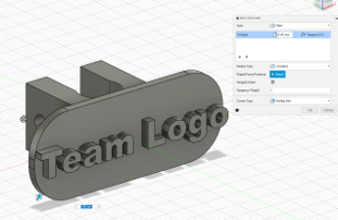
8. Final Logo Body
- This is how the logo body should look.
![]()
🔹 Step 5: Create the Pipe Clamp
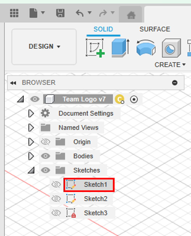
1. Open Sketch1
- Double-click Sketch1 in the Browser.
2. Draw Clamp Rectangle
- Place a rectangle centered within the logo rectangle.
3. Extrude the Clamp Rectangle
- Exit sketch mode.
- Use the Extrude tool and set the depth to 20 mm.
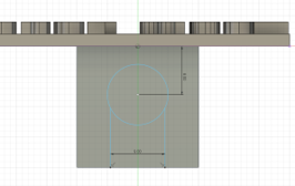
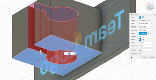
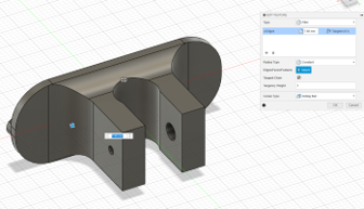
4. Create Sketch for the Pipe Hole
- Create a sketch on the top face of the clamp.
- Draw a circle 8 mm from the logo, centered left-to-right.
- Add two parallel lines from the circle to the rectangle edge (to allow pipe insertion and locking).
5. Extrude the Hole
- Exit the sketch.
- Use Extrude, select the circle and area between the lines.
- Set Extent Type to "To Object" and select the opposite face of the clamp.
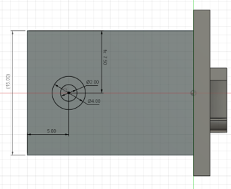
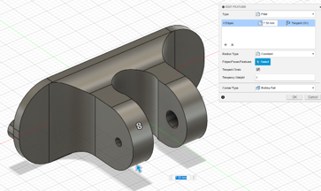
6. Create a Clamp Locker
- Create a sketch on the right side of the clamp.
- Draw two circles (2 mm and 4 mm diameter), 5 mm from the back, vertically centered.
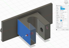
7. Extrude the Clamp Locker
- Use Extrude to create the 4 mm hole. Set Extent Type to "To Object".
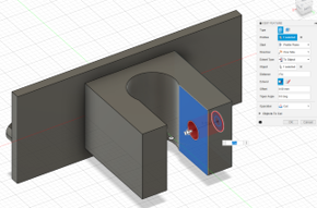
- Use Extrude to create the 2 mm hole. Set Start to "Object" (the inside face), and Extent Type to "To Object".
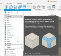
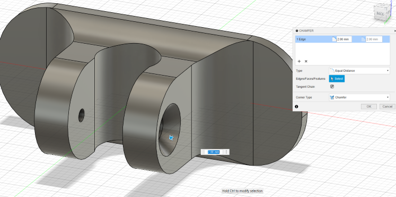
8. Use Fillet to Smooth Edges
- Select the Fillet tool from the Create menu.
- Choose the edges to smooth and set the radius to 9 mm (or any value).
- Repeat for other edges as desired:
9. Create Chamfer for the Locker Screw
- Select Chamfer from the Create menu.
- Select the hole edge and set the chamfer value to 2 mm.
🔹 Final: Logo Body Finished
![]()