PWM Control with CTIMER on the FRDM–MCXN947 Board
🎯 Objective:
Learn how to configure and generate PWM signals using the CTIMER peripheral in MCUXpresso IDE on the FRDM–MCXN947 development board.
🔍 What are CTIMER and PWM?
CTIMER (Counter/Timer) is a versatile on-chip peripheral found in NXP microcontrollers that can operate as a timer, counter, or PWM generator. PWM (Pulse-Width Modulation) is a technique to encode analog values using a digital signal by varying the duty cycle. It is widely used for motor control, LED dimming, and signal generation.
🖥️ Tools and Requirements
- IDE: MCUXpresso IDE (v11.5.0 or later)
- Board: FRDM–MCXN947 development kit
- Compiler: GNU Arm Embedded Toolchain (bundled with IDE)
- Connectivity: USB cable for board programming and debugging
🧭 Workspace Overview
When you open your project in MCUXpresso IDE:
- Peripherals Perspective: Configure on-chip peripherals visually.
- Problems View: Displays configuration errors and quick-fix suggestions.
- Pins Perspective: Assign and route physical pins to peripheral functions.
- Project Explorer: Browse source files and configuration.
✏️ Step-by-Step PWM Configuration
🧱 Main Steps
- Enable CTIMER Driver in Peripheral Drivers section.
- Set Mode to PWM and configure clock prescaler.
- Define PWM Channels and default duty cycles.
- Route Pins in Pins Perspective or via quick-fix.
- Generate Code and call the PWM update function in your application.
🔹 Step 1: Open Peripherals Perspective
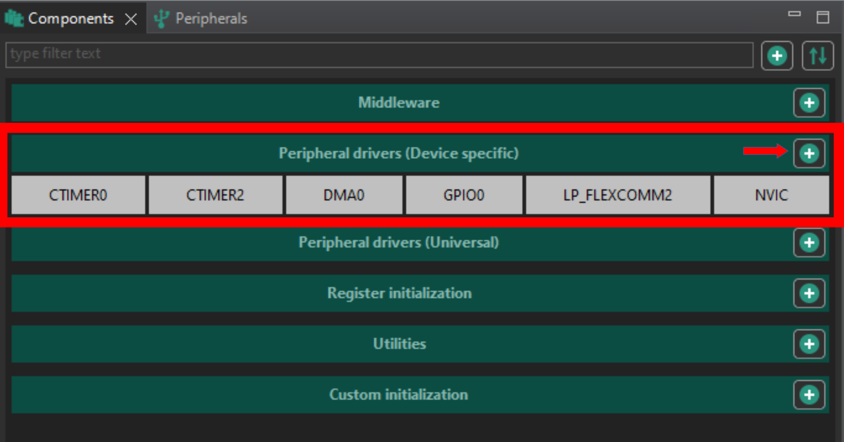
- In MCUXpresso IDE, click the Peripherals tab or switch via the perspective icon.
- Expand Peripheral Drivers (Device specific) and click + to add a new driver.
🔹 Step 2: Enable CTIMER and Set Mode
-
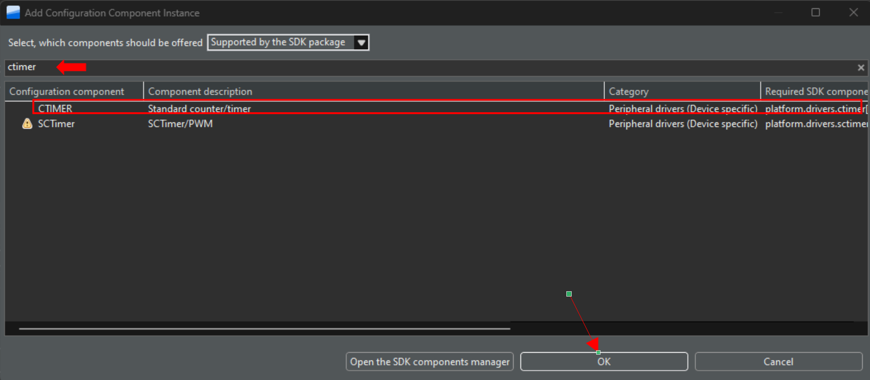
Search for ctimer in the drivers list and press OK.
-
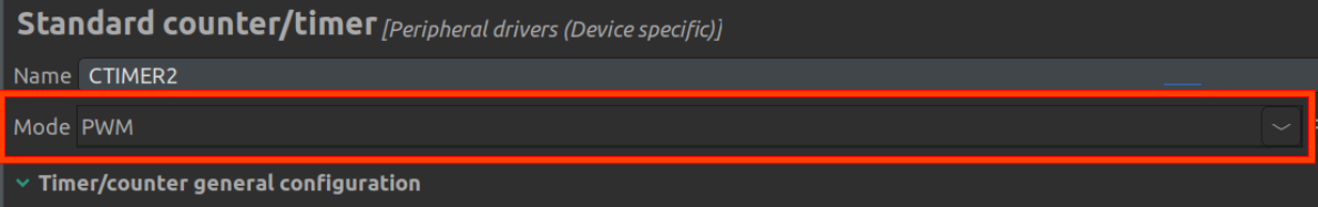
In the CTIMER instance list, select the desired timer (e.g., CTIMER1).

-
Under Mode, choose PWM.
🔹 Step 3: Resolve Clock Errors
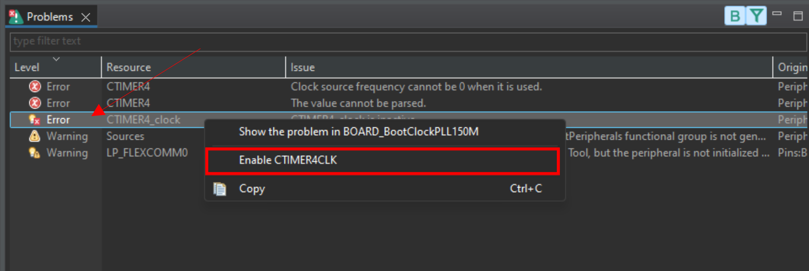
- Go to the Problems tab (right corner).
- Right-click any CTIMER_clock error (bulb icon) and apply the suggested fix to enable its clock.
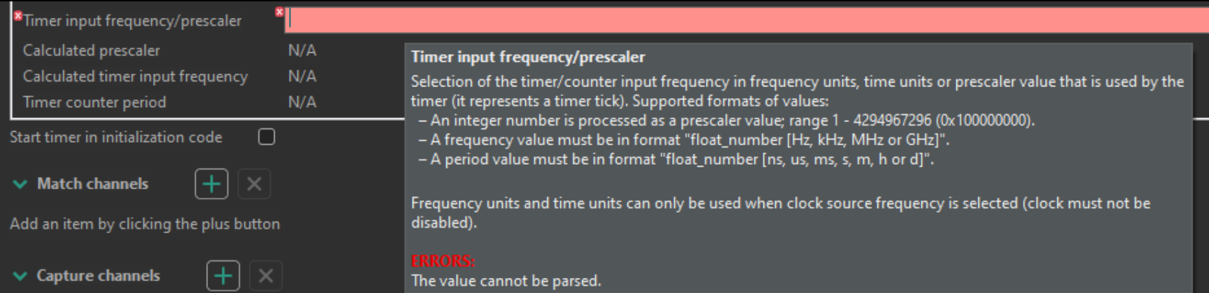
🔹 Step 4: Configure Timer Frequency and Prescaler
-
In the CTIMER settings, set the Input Clock Frequency or Prescaler so that the timer base frequency supports your desired PWM frequency.
- Explanation: The prescaler divides the bus clock to achieve a timer tick rate matching the PWM period requirements.
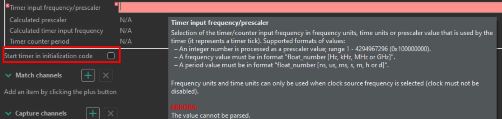
-
Start the timer in initialization code.
- Explanation: The CTIMER counter must be running for PWM outputs to be generated. Check “Start the timer in initialization code” so the timer starts automatically during peripherals initialization—no manual CTIMER_StartTimer(...) call needed.
- Explanation: The CTIMER counter must be running for PWM outputs to be generated. Check “Start the timer in initialization code” so the timer starts automatically during peripherals initialization—no manual CTIMER_StartTimer(...) call needed.
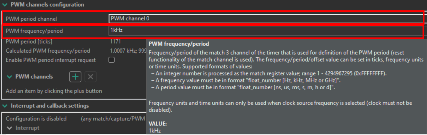
-
Enter the PWM Frequency for the selected CTIMER channel.
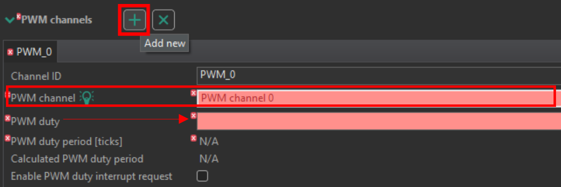
🔹 Step 5: Add and Configure PWM Channels
- In the PWM Channels section, click + to add a channel.
- Choose a channel number (1‒n, avoid channel 0) and set the Default Duty Cycle (applied at initialization before runtime updates).
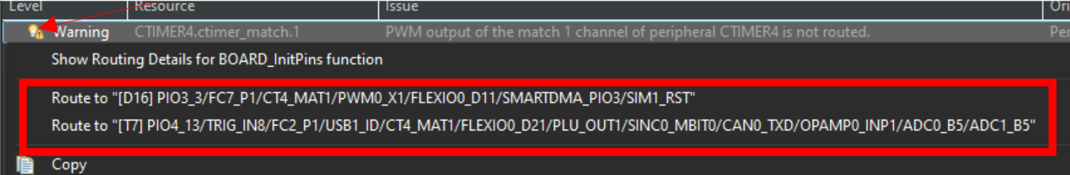
🔹 Step 6: Route the PWM Pin
-
Quick-Fix Method: In the Problems view, right-click the PWM pin assignment error and accept the suggested route.
-
Pins Perspective Method: Switch to Pins, search for
ctimer<no>:match<pwm_channel_no>, enable the pin, and set Direction to Output (Routing Details - bottom section).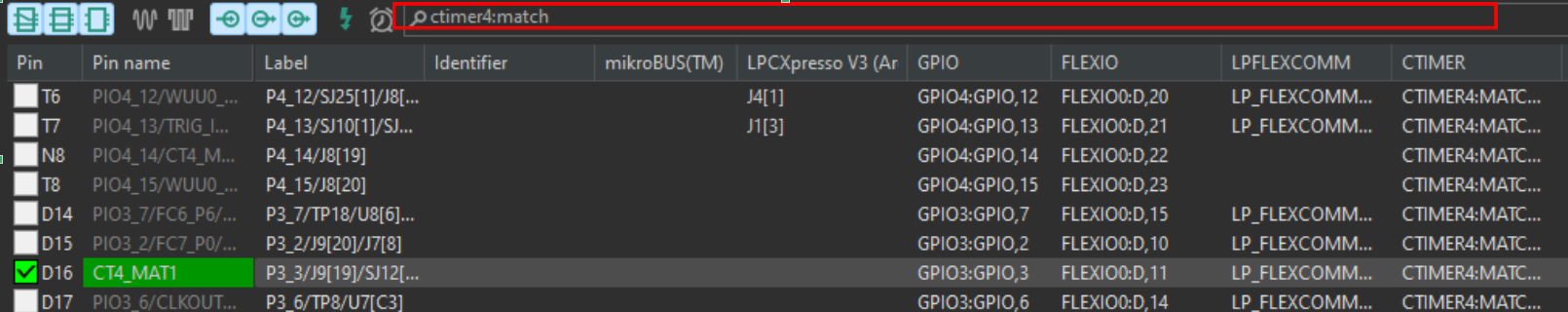
Tip: Verify the routed pin is available on a board header by consulting the FRDM–MCXN947 schematic.
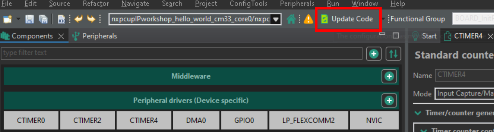
🔹 Step 7: Generate Code
- After completing configuration, click Update Code to regenerate driver initialization based on your configuration.
🔹 Step 8: Using PWM in Application Code
Call the generated driver function to update duty cycle at runtime:
CTIMER_UpdatePwmDutycycle(
    CTIMER<no>_PERIPHERAL,                      // e.g., CTIMER1_PERIPHERAL
    CTIMER<no>_PWM_PERIOD_CH,                   // the period channel defined in config
    CTIMER<no>_PWM_<pwm_channel_no>_CHANNEL,    // the channel index
    dutyPercent                                // new duty cycle in percent (integer)
);
⚙️ Advanced: Using Match Registers for Precise Duty Control
When you need more precise control—for example, fractional duty cycles for servos or fine-grained LED brightness—you can calculate and write directly to the timer's match registers.
uint32_t periodTicks = CTIMER<no>_PERIPHERAL->MR[CTIMER<no>_PWM_PERIOD_CH];
uint32_t pulseTicks  = (uint32_t)((periodTicks * dutyPercent) / 100.0);
CTIMER<no>_PERIPHERAL->MR[<channelIndex>] = pulseTicks;
Explanation of Ticks and Duty Translation
-
periodTicks: Total number of timer ticks for one full PWM period. It is read from the match registerMR[CTIMER<no>_PWM_PERIOD_CH]which defines the period channel. -
Timer Tick Duration: With a bus clock of, say, 48 MHz and a prescaler value
P, each tick occurs everyP / 48 000 000seconds. -
dutyPercent: Desired duty cycle as a percentage (0–100). -
Calculating
pulseTicks:- Multiply
periodTicksbydutyPercent / 100.0to get the fractional portion of the period. - Cast to
uint32_tto obtain an integer tick count.
- Multiply
-
Writing to
MR[channelIndex]: Setting this register tells the timer when (in ticks) to toggle the PWM output from high to low, achieving the specified duty cycle.
This method translates your percentage-based duty into concrete timer ticks, leveraging the full resolution of the CTIMER peripheral for precise PWM control.
🎉 Congratulations!
You have successfully configured and generated PWM signals on the FRDM–MCXN947 board using the CTIMER peripheral. Explore varying frequencies, multiple channels, and advanced timer features to build complex control applications.