Introduction
Embassy is a modern, async embedded framework for Rust. It provides efficient, non-blocking abstractions for microcontrollers.
First, clone the embassy-rs repository.
git clone [email protected]:embassy-rs/embassy.git
cd embassy
Environment setup
For those of you working in Visual Studio Code, the Embassy project has support for rust-analyzer. In order to properly set it up, make sure you correctly open the project's root folder (embassy), and modify the workspace settings according to the example bellow.
{
  // ...

  // Uncomment the target of your chip.

  //"rust-analyzer.cargo.target": "thumbv6m-none-eabi",
  "rust-analyzer.cargo.target": "thumbv7m-none-eabi",
  // "rust-analyzer.cargo.target": "thumbv7em-none-eabi",
  //"rust-analyzer.cargo.target": "thumbv7em-none-eabihf",
  //"rust-analyzer.cargo.target": "thumbv8m.main-none-eabihf",
  "rust-analyzer.cargo.features": [
    // Comment these features
    // "stm32f446re",
    // "time-driver-any",
    // "unstable-pac",
    // "exti",
    // "rt",
  ],
  "rust-analyzer.linkedProjects": [
    "examples/stm32f4/Cargo.toml",
    // To work on the examples, comment the line above and all of the cargo.features lines,
    // then uncomment ONE line below to select the chip you want to work on.
    // This makes rust-analyzer work on the example crate and all its dependencies.
    // "examples/mspm0c1104/Cargo.toml",
    // "examples/mspm0g3507/Cargo.toml",
    // ...
  ],
}
Blink an LED
Fortunately, Embassy provides a variety of examples implemented for a multitude of hardware platforms, our STM32F429ZI included. Examples for our board can be found in the examples/stm32f4 crate. Multiple examples can be found in the src folder, organized as separate binaries. To flash one of the examples, simply run:
cd examples/stm32f4
cargo run --bin <EXAMPLE>
Go ahead and run the blinky example. You should get an output similar to this.
cargo run --bin blinky
    Compiling proc-macro2 v1.0.97
    Compiling unicode-ident v1.0.18
    ...
    Compiling embassy-net v0.7.0 (/Users/danut/Work/eurotock/ipw-repos/embassy/embassy-net)
    Finished `dev` profile [unoptimized + debuginfo] target(s) in 12.33s
     Running `probe-rs run --chip STM32F429ZITx target/thumbv7em-none-eabi/debug/blinky`
      Erasing ✔ 100% [####################] 128.00 KiB @  44.41 KiB/s (took 3s)
  Programming ✔ 100% [####################]  81.00 KiB @  31.50 KiB/s (took 3s)                         Finished in 5.46s
0.000000 [TRACE] BDCR ok: 00008200 (embassy_stm32 src/rcc/bd.rs:221)
0.000000 [DEBUG] flash: latency=0 (embassy_stm32 src/rcc/f247.rs:264)
0.000000 [DEBUG] rcc: Clocks { hclk1: MaybeHertz(16000000), hclk2: MaybeHertz(16000000), hclk3: MaybeHertz(16000000), hse: MaybeHertz(0), lse: MaybeHertz(0), lsi: MaybeHertz(0), pclk1: MaybeHertz(16000000), pclk1_tim: MaybeHertz(16000000), pclk2: MaybeHertz(16000000), pclk2_tim: MaybeHertz(16000000), pll1_q: MaybeHertz(0), plli2s1_p: MaybeHertz(0), plli2s1_q: MaybeHertz(0), plli2s1_r: MaybeHertz(0), pllsai1_q: MaybeHertz(0), rtc: MaybeHertz(32000), sys: MaybeHertz(16000000) } (embassy_stm32 src/rcc/mod.rs:71)
0.000152 [INFO ] Hello World! (blinky src/bin/blinky.rs:13)
0.000915 [INFO ] high (blinky src/bin/blinky.rs:18)
0.302062 [INFO ] low (blinky src/bin/blinky.rs:22)
3-bit Counter
For this task, you will have to implement a 3-bit counter, using the 3 on-board LEDs and the USER button on board.
You will need to create a new binary in the src/bin folder you can name counter-3bit.rs, starting from the blinky.rs example.
#![no_std]
#![no_main]

use defmt::*;
use embassy_executor::Spawner;
use embassy_stm32::gpio::{Level, Output, Speed};
use embassy_time::Timer;
use {defmt_rtt as _, panic_probe as _};

#[embassy_executor::main]
async fn main(_spawner: Spawner) {
    let p = embassy_stm32::init(Default::default());
    info!("Hello World!");

    let mut led = Output::new(p.PB7, Level::High, Speed::Low);

    loop {
        info!("high");
        led.set_high();
        Timer::after_millis(300).await;

        info!("low");
        led.set_low();
        Timer::after_millis(300).await;
    }
}
The first step is figuring out the pins the other two LEDs are connected to. To do so, you can consult the board's User Manual.
#[embassy_executor::main]
async fn main(_spawner: Spawner) {
    let p = embassy_stm32::init(Default::default());
    info!("Hello World!");

    let mut led0 = todo!("Replace me");
    let mut led1 = Output::new(p.PB7, Level::High, Speed::Low);
    let mut led2 = todo!("Replace me");

    loop {
        // ...
    }
}
Next, you will have to instantiate the button. We will want to use one of the external interrupt lines, in order to use the asynchronous methods for the user button.
let button = ExtiInput::new(p.PC13, p.EXTI13, Pull::Down);
Make sure to fix all the import errors.
Now, inside the main loop. Await for the button to be pressed in order to update the "3-bit display".
let mut counter = 0;
loop {
    button.wait_for_high().await;
    counter = (counter + 1) % 7;

    // Depending on the value of each of the three bits,
    // set the LEDs high or low
}
Improved BinaryCounter
With everything in place, here comes the question of extending the functionalities. We would like for this display mechanism to be painlessly extensible to work with any number of LEDs. The quick and painless answer to this problem is generics. We must define a generic BinaryCounter.
struct BinaryCounter<'a, const N: usize> {
    inner_counter: usize,
    leds: [Output<'a>; N],
}

impl<'a, const N: usize> BinaryCounter<'a, N> {
    fn new(leds: [Output<'a>; N]) -> Self {
        Self {
            inner_counter: 0,
            leds,
        }
    }
}
Next, we will define the API for interacting with our display. We will have two methods, increment which will increase the inner counter's value by one unit and display, which will update the LEDs state.
impl<'a, const N: usize> BinaryCounter<'a, N> {
    fn new(leds: [Output<'a>; N]) -> Self {
        Self {
            inner_counter: 0,
            leds,
        }
    }

    /// This function increases the inner counter
    fn increment(&mut self) {
        core::todo!()
    }

    /// This function updates the state of the LEDs
    /// according to the `inner_counter` value
    fn display(&mut self) {
        core::todo!()
    }
}
With the interface in place, we can write the main function.
#[embassy_executor::main]
async fn main(_spawner: Spawner) {
    let p = embassy_stm32::init(Default::default());
    info!("Binary Demo!");

    // TODO: `Output` definition

    let mut bc = BinaryCounter::new([led0, led1, led2]);

    let mut button = ExtiInput::new(p.PC13, p.EXTI13, Pull::Down);

    loop {
        bc.display();
        button.wait_for_high().await;
        bc.increment();
    }
}
I2C
The Inter-Integrated Circuit (I2C) is a synchronous, multi-controller/multi-target communication protocol. Similarly to the SPI, it allows data transfer between a controller and one or more peripheral ICs, but it uses only 2 wires (1 data line and 1 clock line, making it half-duplex) and has a different way of addressing the peripherals: using their unique addresses.
Configuration

I2C transmission uses 2 lines:
- SCL - Serial CLock line - clock is generated by the controller - used to synchronize communication between the controller and the targets
- SDA - Serial DAta line - carries data between the controller and the addressed target
- targets read data from SDA only when the clock is low
- targets write data to SDA only when the clock is high
The communication is half-duplex. This means that data is transmitted only in one direction at a time, since there is only one data line that can be used both for sending data to the target and receiving data from the target.
The SDA and SCL wires are never actually driven (set to LOW/HIGH) by the controller/peripherals. The line is controlled by either pulling the line low or releasing the line high.
When the line is pulled down, this means that it is connected directly to GND. This electronically translates to LOW.
When the line is released, or pulled up, this means that it connects back to 3V3 (which we can consider as being the "default" state of the wire) through a pull-up resistor. This electronically translates to HIGH.
This is called open-drain connection. You can read more about how it works here, at section 2.2.
Data transmission
Each target is associated with a unique address. The controller uses this address to initiate communication with that target. This address can either be 7 or 10 bits.
Initiation
Before the transmission, both the SCL and SDA lines are set to HIGH. First thing the controller does is to signal a start condition by pulling the SDA line to LOW. All targets understand that the communication is about to commence and listen on the SDA line. Next, the controller starts the clock and begins to write the address of the target it wants to talk to, followed by a command bit that signifies whether the controller wants to read from the target or write to it. Whichever target recognizes its address, responds with an ACK (acknowledged), by pulling the SDA to LOW. If no target responds and the SDA stays HIGH, then it is considered a NACK (not acknowledged). Afterwards, the data transmission can begin.
Transmission
Depending on the command bit (R/W), either the controller or the target begins to send data over the SDA line. Data is sent one byte at a time, and then acknowledged by the receiver. One sequence of a data byte and ack is called a frame.
During the communication, data can be:
- written to the
SDAline only whenSCLisLOWor - read from the
SDAline only whenSCLisHIGH.
End
To end the transmission, the controller signals a stop condition. This is done by releasing the SCL line to HIGH, and then also releasing the SDA line. Since data can be written only when SCL is LOW, the target understands that this is a special event, that means that the communication has ended.

For 10-bit addresses, the controller first issues a specific sequence of bits. This sequence is reserved, therefore targets with 7-bit addresses are prohibited from having addresses that start with this sequence. These bits mark the fact that the controller is attempting to initiate communication with a target with a 10-bit address, so all 7-bit targets ignore the SDA line once they recognize this sequence. After the special sequence, the controller sends the upper 2 bits of the address and the command bit, then waits for an ack from the target(s) that have an address that begins with these 2 bits. Afterwards, it sends the rest of the address, and waits for an acknowledgement from the target.

I2C in Embassy
These are the I2C imports we will be using. We will use the functions provided by the embedded_hal_async crate, since these are standard and used by most frameworks.
use embassy_stm32::i2c::I2c;
use embassy_stm32::{bind_interrupts, i2c, peripherals};
I2c trait importingWe use I2c as _ from embedded_hal_async because in order to use the trait methods, we need to import it.
We start by initializing the peripherals.
let peripherals = embassy_stm32::init(Default::default());
Next, we declare the pins we will be using for the SDA and SCL lines. We can find which pins of the Raspberry Pi Pico have these functions by looking at the pinout.
let sda = peripherals.PIN_X;
let scl = peripherals.PIN_Y;
We then initialize our I2C instance, using the pins we defined earlier and a default configuration. It's recommended to use the asynchronous version, since it won't block the executor.
/// I2C
let mut i2c = I2c::new_async(peripherals.I2CX, scl, sda, Irqs, peripherals.DMAX_CHX, peripherals.DMAX_CHX, Default::default());
The first argument of the new function is the I2C channel that will be used. Each has multiple sets of pins that can be used for and you can find them marked in blue on the pinout diagram.
The Irqs variable refers to the interrupt that the I2C driver will use when handling transfers. We also need to bind this interrupt, which depends on the I2C channel we are working with.
bind_interrupts!(struct Irqs {
    I2C1_EV => i2c::EventInterruptHandler<peripherals::I2C1>;
    I2C1_ER => i2c::ErrorInterruptHandler<peripherals::I2C1>;
});
I2cConfig and I2cInterruptHandler are renamed importsBecause of the Embassy project naming convention, multiple Configs and InterruptHandlers can exist in one file. To solve this without having to prefix them with their respective module in code every time we use them (i.e use i2c::Config and i2c::InterruptHandler), in the code examples above I2cConfig and I2CInterruptHandler are renamed imports:
use embassy_stm32::i2c::{I2c, InterruptHandler as I2CInterruptHandler, Config as I2cConfig};
Reading from a target
To read from a target, we will be using the read async function of the I2C driver.
The function takes 2 parameters:
- the address of the target we are attempting to receive the data from
- the receiving buffer in which we will store the data received from the target
The following example reads two bytes from the target of address 0x44.
const TARGET_ADDR: u16 = 0x44;
let mut rx_buf = [0x00u8; 2];
i2c.read(TARGET_ADDR, &mut rx_buf).await.unwrap();
Writing to a target
To write data to a target, we will be using the write async function of the I2C driver.
This function also takes 2 parameters:
- the address of the target we are attempting to transmit the data to
- the transmitting buffer that contains the data we want to send to the target
The following example writes two bytes to the target of address 0x44.
const TARGET_ADDR: u16 = 0x44;
let tx_buf = [0x01, 0x05];
i2c.write(TARGET_ADDR, &tx_buf).await.unwrap();
We can also use write_read if we want to perform both a write and a read one after the other.
i2c.write_read(TARGET_ADDR, &tx_buf, &mut rx_buf).await.unwrap();
AT24C256 EEPROM
The AT24C256 is a 256-kilobit Electrically Erasable Programmable Read-Only Memory (EEPROM) device that communicates using the I2C protocol. It is commonly used for storing non-volatile data, such as configuration settings or calibration data, which need to persist even when the device is powered off.
Device Addressing
The AT24C256 uses a 7-bit I2C address, with the most significant 5 bits fixed as 10100. The remaining 2 bits are configurable by connecting the A1 and A0 pins to either GND or VCC, allowing up to 4 devices to be connected on the same I2C bus. Knowing the state of the pins, you can determine the address using the formula: 0x50 | (A1 << 1) | A0. To determine the address of the EEPROM used by our board, you can check the schematic or perform an I2C scan.
Memory Organization
The memory is organized into 32,768 bytes, divided into 512 pages of 64 bytes each. Each byte can be accessed individually, or multiple bytes can be written/read in a single operation using page addressing.
Reading from the AT24C256
To read data from the EEPROM, you first need to write the memory address you want to read, then read the byte at that memory location. Because we are working with 32,768 bytes of memory (which is 215 bytes), we are working about 2-byte addresses that need to be sent High byte first (big endian).
let mem_addr: u16 = 0xCAFE; // 16 bit address
let memory_address: [u8; 2] = mem_addr.to_be_bytes(); // `be` stands for big endian
let mut data: [u8; 1] = [0];

i2c.write_read(EEPROM_ADDR, &memory_address, &mut data).await.unwrap();
The AT24C256 supports sequential reads. After the EEPROM sends a data word (byte), if the microcontroller sends a responds with an ACK instead of a Stop Condition the memory will continue to increment the internal data word address and serially clock out sequential data words. When the memory address limit is reached, the data word address will "roll over" (begin writing from the beginning) and the sequential read will continue.
This means that we can read multiple consecutive bytes:
let mem_addr: u16 = 0xBABE; // 16 bit address
let mem_buff: [u8; 2] = mem_addr.to_be_bytes(); // `be` stands for big endian
let mut data: [u8; 10] = [0; 10];

i2c.write_read(EEPROM_ADDR, &mem_buff, &mut data).await.unwrap();
Writing to the AT24C256
The EEPROM supports the writing of up to 64 bytes (one page) in a single transaction. The microcontroller performs a write transaction where the first two bytes are the 16-bit memory location in big endian format, followed by a number of bytes that should be written, starting from that respective address. The particularity of this memory module is that, for a write within a page when reaching the upper page boundary, the internal data word address would do a "roll over" to the address of the first byte of the same page.
let mem_addr: u16 = 0xBABE; // 16 bit address
let mem_buff: [u8; 2] = mem_addr.to_be_bytes(); // `be` stands for big endian
let data: [u8; 8] = [0xCA, 0xFE, 0xBA, 0xBE, 0xDE, 0xAD, 0xBE, 0xEF];

let mut tx_buf = [0x00; 8 + 2];
tx_buf[..2].copy_from_slice(&mem_buff);
tx_buf[2..].copy_from_slice(&data);

i2c.write(EEPROM_ADDR, &tx_buf).await.unwrap();
After each complete memory write transaction, the EEPROM an internally-timed write cycle of roughly 5ms. If you have to perform a series of consecutive writes, make sure to space them out appropriately.
eeprom24x crate
To simplify the interfacing with the non-volatile memory for your project, you can use the eeprom24x crate. It is a is a platform agnostic Rust driver for the 24x series serial EEPROM, based on the embedded-hal traits. This means that you will not be able to harness the power of the async executor, and you will need to use the conventional blocking API.
Asynchronous basics
Until now you've only worked with simple (almost) serial programs. However, not all programs can be designed to run serially/sequentially. Handling multiple I/O events concurrently usually requires separate parallel tasks. For example, reading a button press while blinking an LED. A single loop would block the button reading event while waiting for the timer to finish.
To address this issue, we would need to spawn a new task in which we would wait for the button press, while blinking the LED in the main function.
The signature of the task that toggles the LED when the button is pressed would need to receive both an Input and Output as arguments.
#[embassy_executor::task]
async fn button_task(mut led: Output<'static>, mut btn: ExtiInput<'static>) {
    loop {
        //  TODO:
        //  * `await` button rising edge
        //  * print message with `info!`
        //  * toggle LED
    }
}
In the main function, tasks can be spawned using the Spawner provided as an argument.
#[embassy_executor::main]
async fn main(spawner: Spawner) {
    let p = embassy_stm32::init(Default::default());

    // TODO: initialize LEDs and button

    spawner.must_spawn(button_task(led, btn));

    loop {
        // Handle other LED blink
    }
}
To periodically blink and LED, you will need to be able to introduce a delay. You can do so manually, by introducing a for loop with a number of steps that takes into account the frequency of the processor. The issue with this method is that it would do a "busy loop" where the processor spends both time and energy doing unproductive instructions.
This approach does not benefit from the underlying async that could schedule another task with available work to be executed. If you want to introduce delays the embassy way, you can do it using the Timer interface, specifically the Timer::after() function which takes a Duration, or the more direct after_milis, after_secs, etc.
Tasks can be reused, in the sense that a task can be spawned multiple times with multiple parameters, the only thing needed is to specify the pool size (i.e number of concurrent tasks that can be spawned) in the task macro.
#[embassy_executor::task(pool_size = 4)]
async fn led_task(mut led: Output<'static>) {
    todo!()
}
Disco lights
Your task is to make the three LEDs blink at different intervals (for example 100ms, 200ms, 300ms) using a single async task that you spawn multiple times.
main taskIf you simply return in the main task, the program would stop. To fix this, you can add an infinite loop in which you either await a Timer future, or use the yield_now().await
async Channels
Up to this point, we did not encounter the problem of communication between tasks. Any peripherals we used across tasks, we passed as parameter. But there are other, more convenient ways to send data to and from tasks. Instead of having to make global, static variables that are shared by tasks, we could choose to only send the information that we need from one task to another. To achieve this, we can use channels.
Channels allow a unidirectional flow of information between two endpoints: the Sender and the Receiver. The sender sends a value through the channel, and the receiver receives this value once it is ready to do so. Until it is ready, the data will be stored inside a queue. Channels in Embassy are Multiple Producer, Multiple Consumer, which means that we can have a channel associated with multiple senders and multiple receivers.
To use a channel in Embassy, we first need to declare a static instance of the channel outside of the main function.
static CHANNEL: Channel<ThreadModeRawMutex, bool, 64> = Channel::new();
ThreadModeRawMutex- the type of Mutex that the Channel internally uses. It is a mutex that can safely be shared between threadsbool- the type of data that is sent through the channel64- the maximum number of values that can be stored in the channel's queue
One thread should send a value, and the other should receive it:
#[embassy_executor::task]
async fn task1() {
    loop {
        Timer::after_secs(1).await;
        CHANNEL.send(true).await;
    }
}

#[embassy_executor::task]
async fn task2(led: Output<'static>) {
    loop {
        let value = CHANNEL.receive().await;
        match value {
            true => led.toggle().unwrap(),
            false => info!("We got something else")
        }
    }
}
Your task is to implement a simple program that toggles the LED state when the User button is pressed, by dividing the work into a task that checks the button state every 10 milliseconds. You can check the state using the is_high() method.
Signal
This is similar to a Channel with a buffer size of 1, except “sending” to it (calling Signal::signal) when full will overwrite the previous value instead of waiting for the receiver to pop the previous value.
It is useful for sending data between tasks when the receiver only cares about the latest data, and therefore it's fine to “lose” messages. This is often the case for “state” updates.
use embassy_sync::signal::Signal;

static SIG: Signal<CriticalSectionRawMutex, ()> = Signal::new();

#[embassy_executor::task]
async fn waiter() {
    SIG.wait().await; // Wait until signaled
    defmt::info!("Signal received!");
}

#[embassy_executor::task]
async fn trigger() {
    SIG.signal(()); // Notify the waiting task
}
Rewrite the previous exercise using the Signal channel, and instead of checking the button every 10ms, simply await a rising edge on the button's pin.
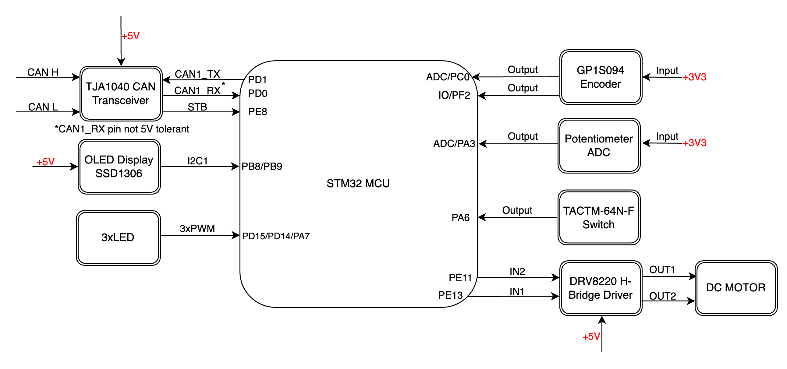
Schematic for the OxidOS shield that you can use in the project: